Accéder au contenu principal
Rechercher
Rechercher dans ce blog
David Romero Trejo
Sécurité des informations | Réseau
Articles
Affichage des articles du octobre, 2016
Tout afficher
octobre 31, 2016
Benefits of Layer 7 Load Balancing
octobre 24, 2016
Inverter Circuit with an 74HC04 Chip
octobre 17, 2016
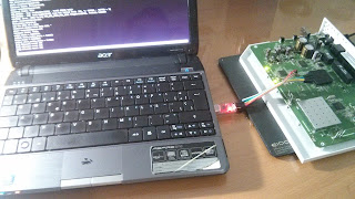
Booting process of broadband routers
octobre 10, 2016
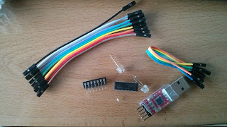
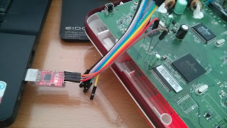
UART connections of an Orange router
octobre 03, 2016
FortiXpert 2016
Articles plus récents
Articles plus anciens
Accueil