UART connections of an Orange router

This
summer, I was building cross
compilations Apps
for broadband commercial routers.
It is not an easy task for me but after hours and hours of working I
got to install and run a “Hello world” application in my
router. However,
Apps and remote access services didn't remain after rebooting thus I
wanted to go further because my goal is to have root access to do
whatever. For this reason, this time, I
wanted to have access by serial port connector to see the booting
process. Let's try with an Orange broadband router.
First,
surfing on Internet, I found that most routers have a serial port
connector called UART
and/or JTAG
which are for programming and access to the console. It
is like the RS232 connectors of computers but it isn't exactly the
same, instead, it is a TTL serial, where a logic high ('1') is
represented by Vcc, often 5V or 3.3V, and a logic low ('0') is 0V.
Therefore, I disassembled the router to
look for this connectors and I was looking the way to connect my
laptop to the router, where I found two options, an USB-to-UART
converter and the BusPirate
electronic device, which is more professional and more expensive too,
thus I bought the cheapest one, the
converter.
 |
| USB-to-UART converter |
Next
step was to identify
the pinout to know which pin is ground (GND), which pin is
transmiting
information (TX) and which pin can receive information (RX). This is
important if we don't want to break/burn the mainboard (PCB)
connecting pines in a wrong way.
Let's begin with the easiest one, the
ground pin.
The
first pin that we have to identify is the ground (GND) pin. What
tools we need? A multimeter. What more we need to know? We have to
identify a ground place too in the mainboard which is easy because
most mainboards have empty places ready for connecting capacitors,
where we can see the minus
symbol meaning ground. Next, connecting
ground to each pin in turn with the multimeter we should look for 0V.
 |
| Identifying the ground pin |
Once
we know which pin is ground (GND), the next
step is to identify the TX pin. This is a
little more difficult because this pin is
going to fluctuate between the Vcc value (3.3 volts) and ground (0
volts). Why? Because when it is transmiting bits of data, we'll see
3.3V, and when it is transmiting “spaces”, we'll see 0V.
Therefore, we need a good multimeter because if it isn't so, the
multimeter will do the average and it will be difficult to identify
the TX pin. Another way to meter is with an oscilloscope, which is
more expensive than a multimeter, or you can even make
your own oscilloscope with your's computer sound card.
 |
| Identifying the TX pin |
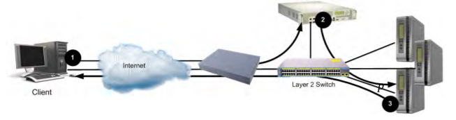
Finally,
we have to identify the RX pin, which is the most difficult one. Why?
Because there isn't a pattern. Therefore, the best way will be by
process of elimination and connecting the serial converter to all
possible receive pins individually, presssing a few keys in our
terminal emulator and seeing what happens until we find out which one
is the RX pin.
 |
| Arcadyan ARV7519RW22-A-LT pinout |
This time, I have fun with an Arcadyan
ARV7519RW22-A-LT router, we'll see in next posts how to
connect the USB-to-UART converter for seeing the booting process and
get the root access in other router as well.
Regards my
friends and remember, test your thought and test whatever you are
thinking.


Commentaires
Enregistrer un commentaire